After purchased my milling machine pre-CNC converted, I continue to find ‘rough edges’, courtesy of its original builder. As the man I bought it from never fully finished the machine, I’m not surprised these never caused him issue.
My recent quest to reduce backlash in all axes lead me to a surprising find. The ‘spider’ couplings used to interface each ClearPath to the axis ball-screw were clearly a budget option, and to make matters worse, the machines builder used jb-weld as a makeshift bore reducer for the servo side. Even more troubling, the couplings affixed to the ball screw were tapped, an odd choice as they are transmitting torque in two directions.
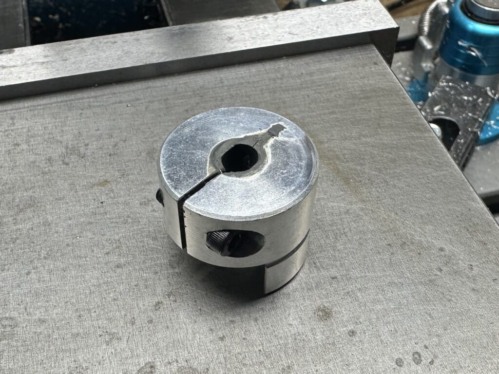

Clearly, this presented itself as an area for immediate improvement, as although the couplings lasted up until this point, that was no guarantee they would last me any longer. This would also make for a fun project as checking part tolerances would involve disassembling the axes as I did not have spare parts to test-fit with.
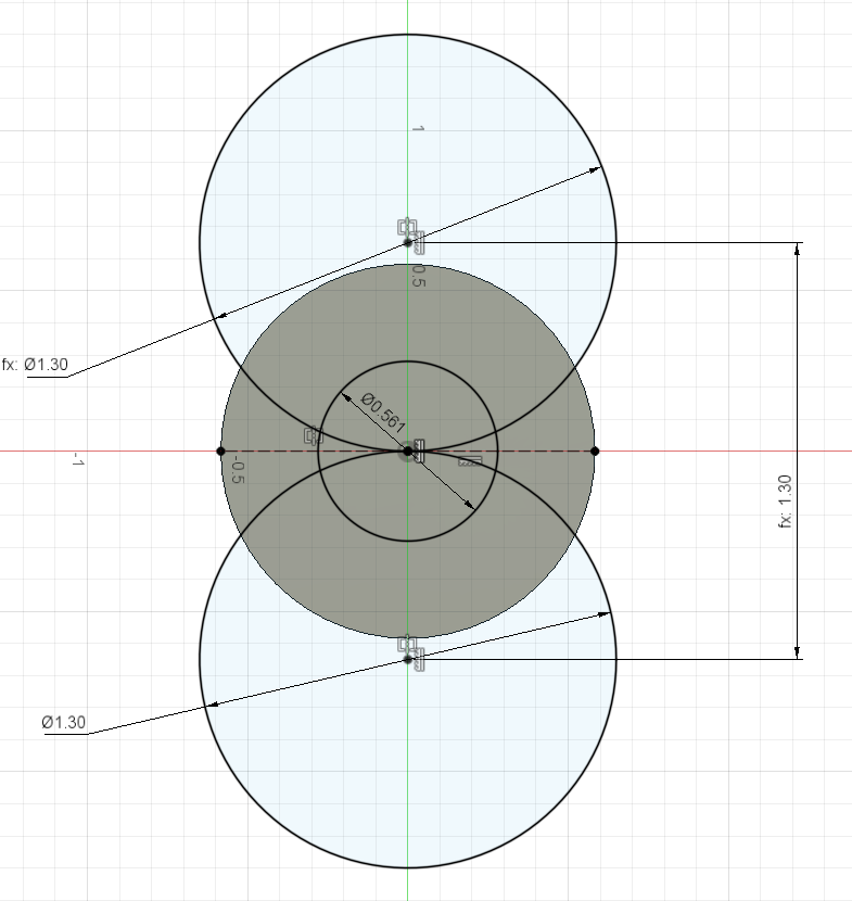
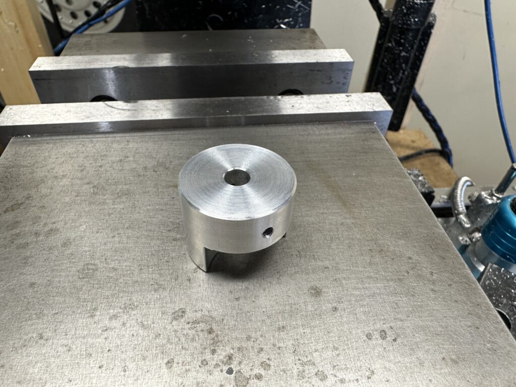
The design process went smoothly, with the only challenging dimension to measure being the large radius cuts from each side of the part. I approximated this dimension by checking the fit of various sockets, and choosing a dimension that was between a socket that was slightly too small, and slightly too large.
The other decision that I made during design was to make these couplers of the set-screw variety, as opposed to the clamp style which they were replacing. This was for three reasons. First, they are much easier to make, second, the previous owner ground flats on the servo shafts, and third, by grinding flats on the ball screw, I would achieve better engagement than simply clamping on top of threads.
Moving from design to CAM, I focused on three critical features. The first being concentricity between the spider and shaft as these couplers account for angular misalignment, not axial. The other two features would be an interference fit between the rubber spider and the part, and a sliding fit for the servo shaft.
Addressing these in order, the concentricity issue was the simplest, as I plan to machine both the spider engagement features, and bore in the same set-up. The harder part would be the interference fit with the rubber spider. To get this dimension perfect, I fine-tuned the final dimensions while machining, using the rubber coupler as a gauge. This was a bit time consuming as it required disassembling the y axis for each fit-check, ensuring I did not change the position of the table.
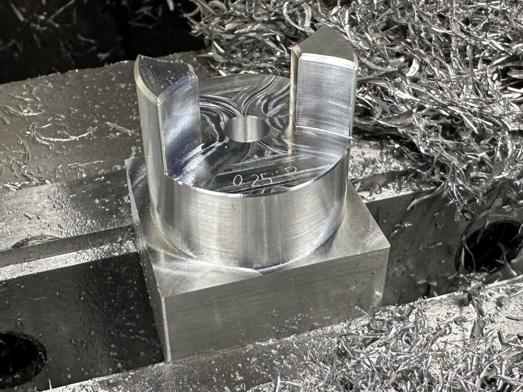
With a couple of skim passes on the key features to bring them into a tight fit, the top-side CAM was complete. Fusion 360 estimated 23 minutes, and I timed around 28, not too shabby for manual tool-changes.
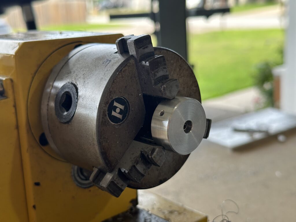
For the final three operations, the part first heads to the bandsaw to remove the extra stock used to hold onto it in this first operation. Then, it’s chucked in the lathe for a simple facing operation to clean-up the bottom of the part. Finally, it’s back to the milling machine to drill and tap set-screw holes.
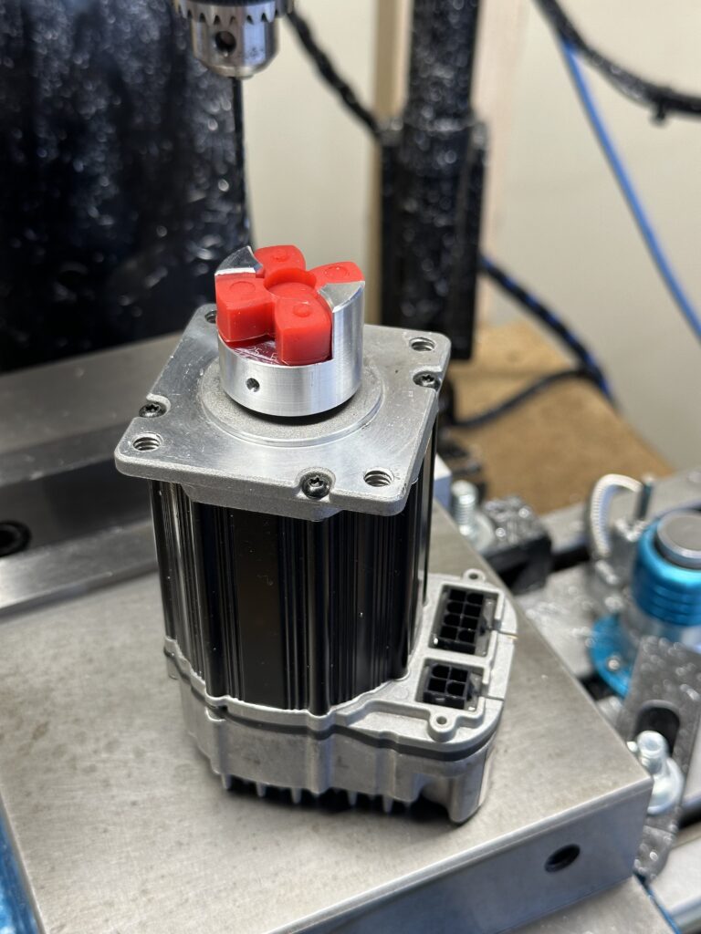
After completing one, I continued to manufacture 3 more to replace each of the suspicious couplings on the X and Y axes.
Concluding the project, I now have much more confidence in the integrity of my machine, and am relieved to have caught this issue when I did.
After installing these new couplings, I measured, and accounted for in software, approximately 3 tenths of backlash in X, and 2.5 in Y.
Another successful project complete, onto the next one.